Who doesn’t love a good alarm sound? Annoy practically everyone with this classic invention. We’ll even include a flashing light for extra effect.
Parts list
What you’ll need




Step 1
Let’s build this
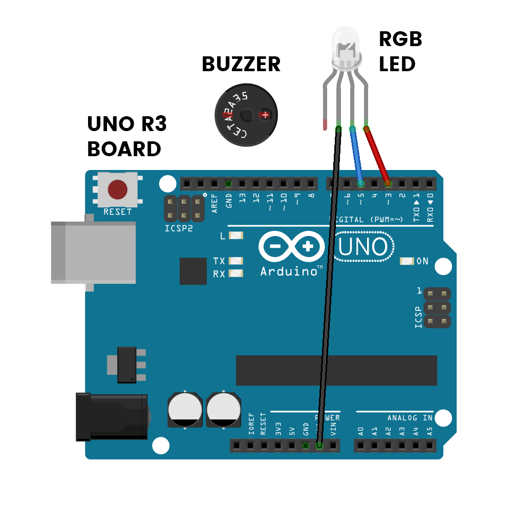
Don’t forget to plug the board into your computer with the included USB cable.
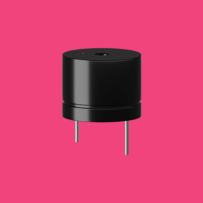
This is the positive leg of the buzzer. It will have a ‘+’ sign on top of it and will also be longer than the other leg.
Apart from the ‘negative’ pin which has a black wire attached, you can tell the difference between all the other pins by the colour of wire attached.
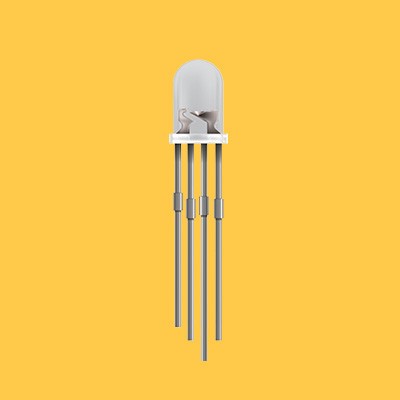
The longest leg of the LED is the ‘negative’ pin and needs to be connected to GND.
Connections
Buzzer
The +LEG is the longer leg.
RGB LED
Use wires to join these.
The -LEG is the LONGEST.
Step 2
Code some chaos
Don’t forget to select your port!
Open the ‘Tools’ menu and select the option that says ‘Arduino/Genuino Uno’.

Copy and paste the sample code
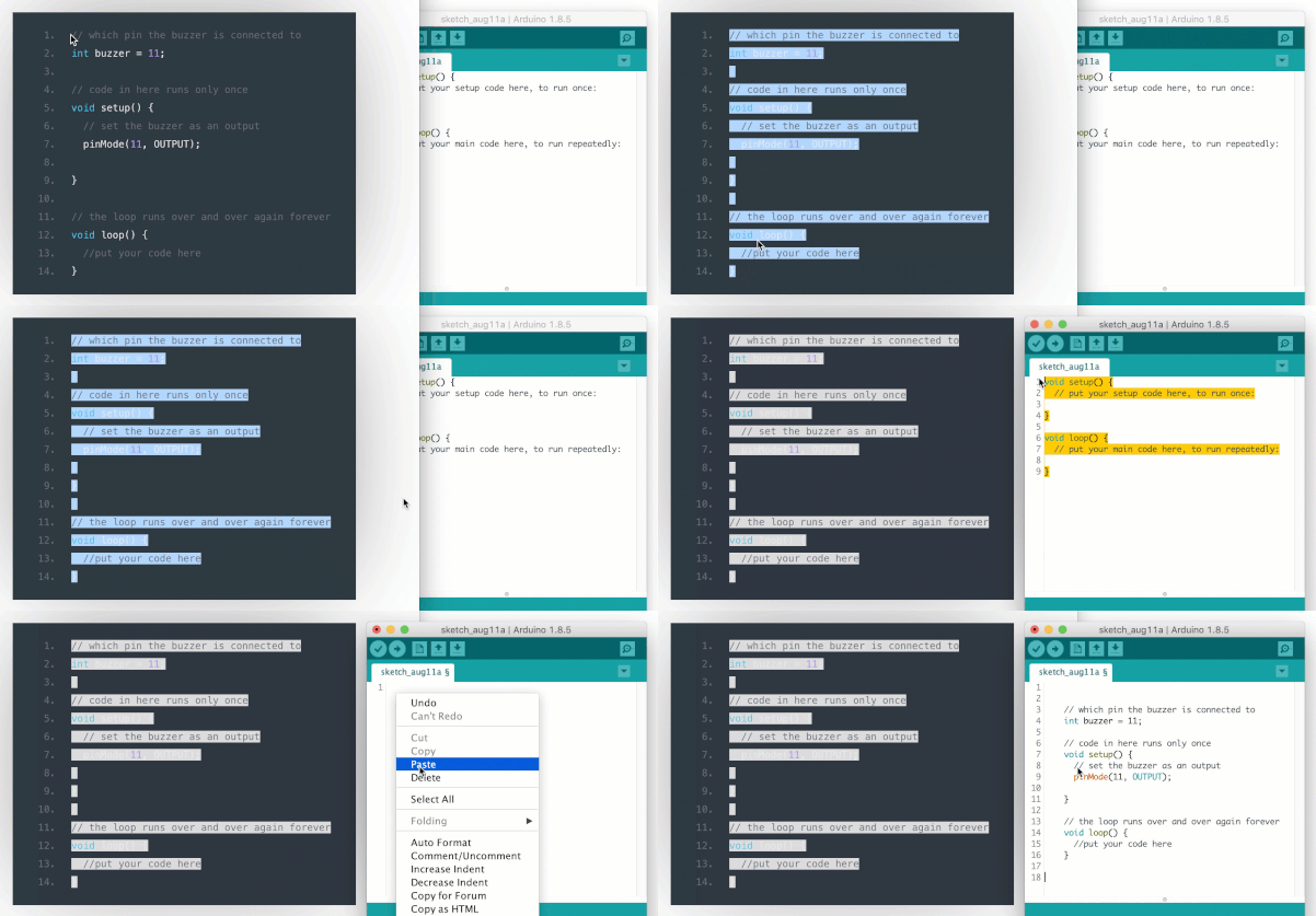
The box to below contains some sample code. Use your cursor to select everything in this box, right click, and select ‘Copy’. Switch to the coding application and delete any text already there. Right click and select ‘Paste’ to insert the sample code.
int buzzer = 11;
int redPin = 3;
int bluePin = 5;
// The time to wait between beeps, in milliseconds
int beepLength = 500;
void setup() {
  // Setup our outputs
  pinMode(buzzer, OUTPUT);
  pinMode(redPin, OUTPUT);
  pinMode(bluePin, OUTPUT);
}
void loop() {
  // Buzzer on with red light on
  analogWrite(buzzer, 255);
  analogWrite(redPin, 50);
  analogWrite(bluePin, 0);
  delay(beepLength);
  // Buzzer off with blue light on
  analogWrite(buzzer, 0);
  analogWrite(bluePin, 50);
  analogWrite(redPin, 0);
  delay(beepLength);
}
Upload the code and test it out
Step 3
Modify the madness
Change the volume level of the alarm
For once, this change isn’t all that exciting. Since the volume of the alarm is already maxed out, the only way the volume can be changed is by bringing it down. But still, if the beeping is a little too loud, then this might be helpful. Line 17 is where the buzzer’s volume is set. Let’s take a look.
  // Buzzer on with red light on
  analogWrite(buzzer, 255);
  analogWrite(redPin, 50);
  analogWrite(bluePin, 0);
The volume here is set with a value anywhere between 0 and 255, where 0 is completely off and 255 is maximum volume. Try a few different values to see what they do to the program.
Change how long each beep goes for
In line 6, you can see that we have set beepLength to equal 500. This is what’s called a variable, but more on that later. Changing this number will alter the length and space between each beep.
// The time to wait between beeps, in milliseconds
int beepLength = 500;
The beepLength is used in the program to control the amount of time that the beep stays on for and also the time that it is off for. This is done with a delay on lines 20 and 25 of the code.
  // Buzzer on with red light on
  analogWrite(buzzer, 255);
  analogWrite(redPin, 50);
  analogWrite(bluePin, 0);
  delay(beepLength);
  // Buzzer off with blue light on
  analogWrite(buzzer, 0);
  analogWrite(bluePin, 50);
  analogWrite(redPin, 0);
  delay(beepLength);
You always have to use a number for a delay to work properly, but because beepLength was given a number (500) earlier on in the code, that is how many milliseconds the delay will go for.
What is cool is that when we change beepLength in line 5 of the code to something else, like 750, the delay time on lines 20 and 25 will change to 750 milliseconds with it.